
Garage Door Opener Sensor Wiring Diagram
As part of constructing a new home garage, many homeowners want to know how to connect their sensors to a garage so they work properly. Understanding the wiring diagram of these sensors not only streamlines the installation process but also equips you with the knowledge to troubleshoot potential issues in the future.
This is very helpful, as it ensures the longevity and reliability of your garage door opener, keeping it functioning smoothly for years to come. In this article, we’ll discuss garage door opener sensor wiring diagram and much more. So, let’s start!
Table of Contents
What Is Garage Opener Sensor Wiring Diagram?
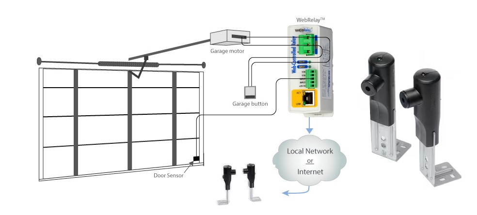
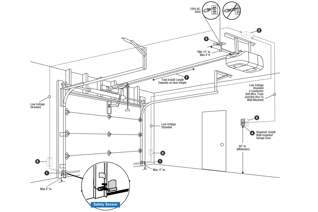
The garage door opener sensor wiring diagram is a critical blueprint that outlines how the sensors, which are safety features of your garage door, are connected to the opener system. This diagram provides clear guidance on the electrical connections necessary to ensure that your garage door reverses automatically if it encounters an obstacle.
Familiarizing yourself with this diagram ensures your garage door opener’s safe and effective functioning. Now that we understand the wiring diagram let’s explore how to connect it to your garage doors.
Related Article: Why Is My Garage Door Sensor Blinking Red?
How to Wire Safety Sensors to a Garage Door Opener
When it comes to installing safety sensors for your garage door opener, these sensors are crucial for ensuring that your garage door stops and reverses if it encounters an obstacle. The process begins with understanding how to connect these sensors to the terminal types on your opener. Here are a few examples of how you can do this:
Quick Connect Plug-In Terminals
This process will explain how to connect these sensors to the terminal types on your opener. Here is what you need to do to connect plug-in terminals:
1. Preparing the Wires:
- Start by removing 7/16-inch of insulation from each wire of the sensors. You will find two wires on each sensor: a solid white wire and another white wire striped with black. This gives you a total of four wires to work with.
2. Connecting the Wires:
- Pair and twist the two white wires with black stripes, one from each sensor.
- Similarly, twist the two solid white wires together, one from each sensor.
3. Attaching to the Motor Unit:
- Find the gray terminal on the motor unit and attach the twisted pair of white-with-black-stripe wires.
- Next, connect the twisted pair of solid white wires to the white terminal, which is located beside the gray terminal on the motor unit.
Related Article: How Long Do Garage Door Opener Sensors Last?
Quick Connect Plug-In Terminals Using Pre-Existing Wires
This section’ll explain how to connect these sensors using pre-existing wires, making the process straightforward and manageable.
1. Preparation of Wires:
- Begin by removing 7/16-inch of insulation off of each wire on the sensors. You will have two types of wires on each sensor: one solid white and the other white striped with black.
2. Wire Splicing and Connections:
- The wire that you splice to the white-with-black-stripe wire from each sensor should be connected to the gray terminal on the motor unit.
- The wire spliced to the solid-white wire from the sensors must be connected to the white terminal, which you will find adjacent to the gray terminal on the motor unit.
Following these steps, you can ensure a secure and correct connection of your garage door opener’s safety sensors.
NOTE! To release or insert wires into the quick connect terminals, push in the tab below the terminal with the tip of a screwdriver.
Openers with Screw Terminals
When you’re installing sensors for garage door openers with screw terminals, it’s important to correctly connect the wires for optimal functionality and safety. Here’s a step-by-step guide:
1. Preparing the Sensor Wires:
- Start by removing 7/16-inch of insulation off of each wire on both sensors. You’ll find two types of wires: solid-white and white-with-black-stripe.
2. Joining the Wires:
- Twist the two white-with-black-stripe wires from each sensor together.
- In the same way, twist the two solid-white wires from each sensor.
3. Connecting to the Motor Unit:
- Attach the twisted white-with-black-stripe wires to screw terminal number 3 on the motor unit.
- Then, connect the twisted solid-white wires to screw terminal number 2 on the motor unit.
Following these steps ensures that your garage door sensors are wired correctly, which is essential for the safe and efficient operation of your garage door opener. Remember, proper wiring is crucial for the longevity and reliability of your garage door system.
Related Article: Why Is My Garage Door Sensor Blinking?
Screw Terminals Using Pre-Existing Wires
When you’re working with pre-existing wires for your garage door sensors and screw terminals, the process requires precision and attention to detail. Here’s a step-by-step guide to ensure a safe and effective installation:
1. Preparing the Wires:
- Begin by stripping off 7/16-inch of insulation from each wire on the sensors. You’ll deal with two types of wires: solid white and white with a black stripe.
2. Splicing and Connecting Wires:
- The wire that you splice with the white-with-black-stripe wire should be connected to screw terminal number 3 on your motor unit.
- Similarly, the wire spliced with the solid-white wire should be attached to screw terminal number 2 on the motor unit.
3. Securing the Connections:
- Once the wires are spliced and connected, make sure to insulate each splice. Electrical tape or wire caps can ensure a safe and secure connection.

Related Article: How to Bypass Garage Door Sensors? 6 Easy Ways
FAQ: People Also Ask
How are garage sensors wired?
To wire garage door sensors, twist the two white wires with black stripes together and then twist the two solid white wires together. Connect the twisted white-with-black-stripe wires to the gray terminal and the twisted solid white wires to the white terminal on the motor unit.
Are garage door sensor wires low voltage?
Garage door sensor wires typically handle low voltage, around 12 volts, and are usually made of thin copper wire. This is because manufacturers often provide specific wiring for these sensors without a set standard for the type of wire used.
Final Thoughts
In conclusion, understanding the garage door opener sensor wiring diagram is crucial for ensuring the safety and efficiency of your garage door system. Proper installation and wiring prevent potential accidents and contribute to the garage door’s smooth operation. It’s important to follow the guidelines meticulously, regardless of whether you’re a professional installer or a DIY enthusiast.
Remember, a well-wired garage door sensor is a key component in the overall functionality of your garage door opener, providing peace of mind and security for your home. With the right approach and attention to detail, you can achieve a successful and safe installation.