
How A 2 Way Switch Wiring Works? Explained

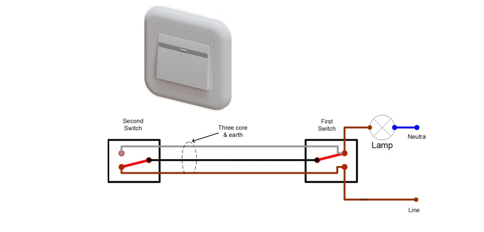
A two-way switch, also known as a staircase switch, is a handy tool for turning on or off lights from two different places. Because of that, it is ideal for places like staircases. In this article, we’ll discuss how this switch works and much more. So, let’s start!
How does a Two-Way Switch Wiring Work? A two-way switch wiring allows control of a single light from two different locations by using two switches connected with three wires (COM, L1, and L2). When either switch is toggled, it completes or breaks the circuit, turning the light on or off accordingly.
Note! This guide is intended to explain the theory behind 2-way switch wiring. It is not a step-by-step installation manual. If you plan to implement this in your home, please consult a professional electrician, as the process involves handling high voltage (either 230V AC or 110V AC, which depends on your location).
Table of Contents
Introduction to Switches
Switches are used everywhere in our daily lives. For example, they can be found in homes, offices, cars, and various electronic devices. They are electrical components that are used to open or close electrical circuits. When it comes to types, there are several types of switches, such as:
- Momentary Switch
- Toggle Switch
- Digital Switch
- Rocker Switch
Each switch type performs the basic function of either interrupting or redirecting the flow of electricity, which means that they open or close a circuit. Most switches, such as those for lights and fans, are two-terminal devices. However, a 2-way switch, which is important for staircase lighting, is slightly different as it is a single pole double throw switch with three terminals.
Related Article: Relay Wiring Diagram (4-Pin & 5-Pin Automotive Relay)
Understanding the Two-Way Light Switch
Before we explain how wiring works, it’s important to understand the 2-way switch itself. This switch has three terminals, typically labeled COM, L1, and L2. In one position, we have COM that connects to L1, and in the other, COM that connects to L2.
This picture shows how a normal household 2-way switch looks:
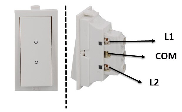
This setup is known as a “break before make” design, meaning the first connection breaks before the second one is made, unlike a standard two-terminal switch, which simply makes or breaks a connection.
How to Wire a 2-Way Switch?
A 2-way switch is particularly useful in staircase lighting, as we mentioned before. There are two primary wiring methods: an older method and a modern, safer version.
Standard 2-Way Switch Wiring
In this traditional method, there are two 2-way light switches that use a three-wire control. Here’s a simple schematic explanation:
- Both COM terminals are connected.
- The L1 terminals of both switches connect to the live wire of the AC supply.
- The L2 terminals of both switches connect to one terminal of the light bulb.
- The other light bulb terminal connects to the AC supply’s neutral wire.
In the picture below, you can see what it looks like:
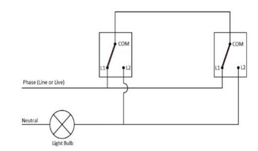
In the schematic, both COM terminals are connected. The L1 terminals of both switches are connected to the live wire of the AC supply.
The L2 terminals of both switches connect to one terminal where the light bulb is placed, while the other terminal with a light bulb connects to the neutral wire of the AC power supply.
This picture clearly shows how the wiring works. In its default state, the light is off. Toggling either switch turns the light on, and toggling any switch again turns it off.
For instance, in the default state, both switches’ COM terminals are connected to their respective L1 terminals. If we toggle Switch 1, connecting its COM terminal to L2, the circuit completes, and the light turns on.
Consider the following scenarios for the light being on:
- COM of Switch 1 is connected to L1, and COM of Switch 2 is connected to L2.
- COM of Switch 1 is connected to L2, and COM of Switch 2 is connected to L1.
This setup can be compared to an XOR gate in digital electronics, where the light’s status depends on the COM terminals’ connection to L1 or L2.
Truth Table for Standard Wiring:
| Switch 1 COM (connected to) | Switch 2 COM (connected to) | Light Status |
|---|---|---|
| L1 | L1 | OFF |
| L1 | L2 | ON |
| L2 | L1 | ON |
| L2 | L2 | OFF |
This table shows that the light’s status is determined by which terminal (L1 or L2) is connected to the COM terminal.
By understanding these basics, we can better understand how a 2-way switch works and consider implementing it in suitable scenarios. We should always prioritize safety and professional guidance for the actual installation. This is very important!
If you want to know more on this topic, be sure to watch this YouTube video:
Alternative Method for Two-Way Switch Wiring
Exploring another wiring design of a 2-wire switch, let’s discuss an older system that can still be found in some older homes. Known as the two-wire control wiring (also known as 2-Wire Control), this method isn’t recommended for modern homes.
If you are considering a new setup or replacing an old one, the previous wiring method should be used. Here, we’ll provide an overview of this alternative wiring method and its drawbacks.
Understanding the Alternative Wiring Method
In the two-wire control setup, both L1 terminals of the switches are always connected, and both L2 terminals are also linked together. The COM terminal, when it comes to the first switch, connects to the phase (or line/live), while the COM terminal of the second switch connects to 1 end of the light bulb, with the other end connecting to the neutral part of the AC supply.
Here is a picture that shows how a two-way switch works:

When in the default state (as shown in the picture above), the light is off. However, toggling either switch will turn the light on. In terms of electronics, this configuration resembles an Ex-NOR Gate.
Truth Table for Alternative Method Wiring (2-Wire Control)
| Switch 1 (COM) | Switch 2 (COM) | Light Status |
|---|---|---|
| L1 | L1 | Off |
| L1 | L2 | On |
| L2 | L1 | On |
| L2 | L2 | Off |
While this method saves on cable, it’s no longer preferred due to several significant drawbacks:
- Potential Mixing of Circuits: The phase and neutral wires may originate from different lighting circuits or breakers, posing a safety risk.
- Electromagnetic Interference: Any current-carrying conductor emits electromagnetic radiation. If live and neutral wires are placed close together, they cancel each other’s EM radiation. However, the neutral and live wires might run separately in this wiring, creating a giant induction loop. This can cause interference with other EM and RF signals.
Related Article: Standard Single-Pole Light Switch Wiring
Two-Way Light Switches Example
Here, I will illustrate a similar setup using a Single-Pole Double-Throw (SPDT) Toggle Switches in combination with an LED. Essentially, a two-way switch functions as an SPDT switch.
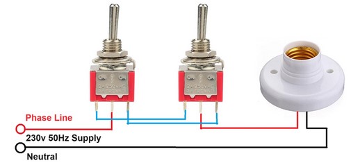
An SPDT Toggle switch has three terminals and operates similarly to a two-way light switch. Here’s a typical SPDT Toggle switch:
I chose the standard wiring method (the 3-wire control) with a 3.8V Li-ion Battery as the power source for the wiring. This setup worked flawlessly, demonstrating the practical application of the concept.
Final Thoughts
Understanding 2-way switch wiring is important to understand better how this lighting works from two locations, particularly in staircases. While traditional and modern wiring methods achieve this, it’s crucial to prioritize safety and consult a professional for installation.
By grasping these concepts, we can enhance the functionality and convenience of our home lighting systems. To avoid potential hazards, ensure your electrical work complies with current standards. I hope this article has helped you. If you have any other questions, feel free to comment below.